Vertical Pump Vibration
May 18, 2018
Primary Factors Affecting Vibration:
- Separation margin to structural natural frequency
Operating on the structural natural frequency of the discharge head motor assembly will result in unacceptable vibration levels. A field margin of +/-10% is recommended to ensure low vibration levels.
A structural natural frequency calculation or analysis (sometimes referred to as a reed critical frequency, RCF) will ensure proper design. Calculation or analysis margin should be larger than required field margin to account for uncertainties, consult the manufacturer for recommendations.
https://www.nationalpumpcompany.com/blog/structural-natural-frequency-analysis
- Balance
The higher the balance grade (lower permissible unbalance) the lower the vibration readings. On a vertical turbine pump, the motor balance primarily drives this based on the location vibration measurements are taken (top of discharge head).
Ordering a motor with a precision balance grade or having the motor field balanced will result in the lowest possible vibration levels.
- Alignment
Misalignment will result in higher vibration levels. Misalignment is typically seen between the top shaft and motor shaft.
Vertical Hollow Shaft (VHS) Motors:
Purchase motor with a steady bushing to help ensure the head shaft is aligned within the motor.
Vertical Solid Shaft (VSS) Motors:
Order precision couplings and or motors with refined based flange and runout tolerances (API). Have optional motor positing jackscrews on the discharge head to allow the motor to be dialed in. Have the pump manufacturer assemble and document runout.
https://www.nationalpumpcompany.com/blog/guide-properly-align-install-vertical-turbine-pumps
Vibration Limits – Acceptance Testing
The flowing limits are for Vertically Suspended (VS1 & VS6) pumps operating at 600 rpm or greater pumping fluids free of solids. Limits vary depending on if the pump is operating within the POR or AOR.
https://www.nationalpumpcompany.com/blog/understanding-preferred-allowable-operating-regions
- Hydraulic Institute – ANSI/HI 9.6.4-2016 “ Rotodynamic Pumps – Guideline for Vibration Measurements and Allowable Values”
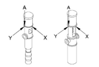
Location for testing: Top of the discharge head, reference figure 9.6.4.2.3.1
Allowable field limits: Reference figure 9.6.4.2.5.1b, overall valuesPOR AOR Below 268 hp (200 kW) 0.13 in/s (3.3 mm/s) rms 0.17 in/s (4.3 mm/s) rms 268 hp (200 kW) & above 0.17 in/s (4.3 mm/s) rms 0.22 in/s (5.6 mm/s) rms POR = Preferred Operating Region
AOR = Allowable Operating Region

Figure 9.6.4.2.3.1 – VS1 & VS6
- American Petroleum Institute – API 610 11th edition “Centrigugal Pumps for Petroleum, Petrochemical and Natural Gas Industries”
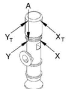
Location for testing: Reference figure 32- Top of discharge head for motors which carry the pump thrust
- Thrust bearing location for pumps which have separate thrust bearing assemblies
Allowable field limits: Reference table 9, all power ratings
POR AOR Overall 5 mm/s (0.20 in/s) rms 6.5 mm/s (0.26 in/s) rms Discrete frequencies 3.4 mm/s (0.13 in/s) rms 4.4 mm/s (0.17 in/s) rms POR = Preferred Operating Region
AOR = Allowable Operating Region

Figure 32 – Locations for taking vibration readings on vertically suspended (VS) pumps
Top of Motor Recommended Vibration Limit
A guideline for vibration limits at the top of the motor has been added as to ANSI/HI 9.6.4-2016 under Appendix C. The recommended limit (not intended to be used as an acceptance criteria) is 1.5 time the limit at the top of the discharge head.
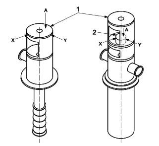
Location for testing: The measurement should be taken near the upper motor bearing. Reference figure C.1.
Allowable field limits: Reference figure C.1, overall values
| POR | AOR | |
| Below 268 hp (200 kW) | 0.20 in/s (5.0 mm/s) rms | 0.26 in/s (6.5 mm/s) rms |
| 268 hp (200 kW) & above | 0.26 in/s (6.5 mm/s) rms | 0.34 in/s (8.5 mm/s) rms |
POR = Preferred Operating Region
AOR = Allowable Operating Region

Figure C.1 – Top of motor locations
Alarm / Shutdown Recommendations
The Hydraulic Institute ANSI/HI 9.6.5-2016 “Rotodynamic Pumps – Guideline for Condition Monitoring” provides a table for recommended alert, alarm and shut-down limits. These limits are based on baseline or acceptance level depending on the type. Reference table 9.6.5.8.4.
| Limit Recommendation | |
| Alert | 130% of baseline |
| Alarm | 150% of acceptance limit |
| Shutdown | 200% of acceptance limit |
Alert = Limit to identify pump vibration level which the pump may need service and begin the repair planning process (ordering of spare parts). This limit can be much lower than the industry standard equipment acceptance. Continued operation at this level is acceptable provided it is below the Alarm and Shutdown limits.
Alarm = Limit at which the maintenance/repair process should begin. Continued operation at this level might be warranted if below Shutdown limits.
Shutdown = Limit at which the pump should be shutdown to prevent severe damage which could be unrepairable. Applying an automatic shutdown should be carefully reviewed to ensure other system equipment, processes and safety are not adversely affected by an automatic shutdown.
Factory Vibration Testing
National Pump Company can provide basic vibration testing in the factory provided that the pump is being tested as a complete unit with the job motor. This test will provide rms velocity vibration measurements in three plane at the top of the discharge head.
National Pump Company does not recommend factory vibration testing for the following reasons:
- The pump installation in the test lab does not represent the installation in the field. This results in the structural natural frequency not matching that of the field, which results in values which may not correlate to the field.
- A valve is used to throttle the pump in order to vary the system curve during the test. This valve can produce large vibration levels due to cavitation, which would not be representative of the pump in the actual system.
National Pump Company guarantees that pumps will meet the applicable vibration limits when installed regardless if factory vibration testing is performed.

